Interactive Resistor Color Code
Supports 4-band and 5-band resistors.
CLICK COLOR BAND TO CHANGE VALUE
📐 Calculation Method
4-band: R = (D1 × 10 + D2) × 10^M ± T%
5-band: R = (D1 × 100 + D2 × 10 + D3) × 10^M ± T%
Where D = digit bands, M = multiplier, T = tolerance
Ceramic Capacitor Code Decoder
Enter 3-digit code (e.g., 104 = 10 + 4 zeros = 100,000 pF = 100 nF)
📐 Calculation Method
Capacitance (pF) = XY × 10^Z
Where code = XYZ (e.g., 104 = 10 × 10^4 = 100,000 pF = 100 nF)
Ohm's Law Calculator
Enter any two values to solve for the others.
📐 Calculation Method
V = I × R (Voltage = Current × Resistance)
I = V / R (Current = Voltage / Resistance)
R = V / I (Resistance = Voltage / Current)
P = V × I = I² × R = V² / R (Power)
LED Resistor Calculator
📐 Calculation Method
R = (V_supply - V_forward) / I_LED
P = (V_supply - V_forward) × I_LED
Where V_forward = LED voltage drop, I_LED = desired current
RC Filter & Time Constant Calculator
Calculate cutoff frequency and time constant for low-pass filters.
📐 Calculation Method
f_cutoff = 1 / (2π × R × C)
τ (tau) = R × C (time constant)
At f_cutoff, signal is attenuated by -3dB (≈70.7%)
Battery Life Estimator
Estimate runtime for battery-powered projects.
📐 Calculation Method
Runtime (hours) = Battery_Capacity (mAh) / Average_Current (mA)
Note: Actual runtime may be lower due to battery efficiency and discharge curves
UART Baud Rate Error Checker
Check error % for common microcontrollers.
📐 Calculation Method
Divisor = Clock_Freq / (16 × Baud_Rate)
Actual_Baud = Clock_Freq / (16 × round(Divisor))
Error % = |Actual_Baud - Desired_Baud| / Desired_Baud × 100
Safe threshold: ≤ 2% error
Engineering Unit Converter
Real-time conversion between common electronics units.
📐 Calculation Method
Resistance: 1 MΩ = 1000 kΩ = 1,000,000 Ω
Capacitance: 1 µF = 1000 nF = 1,000,000 pF
Current: 1 A = 1000 mA = 1,000,000 µA
Universal Pinout Reference
GPIO, power, and peripheral mappings for common dev boards.
ESP32 (WROOM-32)
| Pin | Function | Description |
|---|---|---|
| GPIO 21 | I2C SDA | Data Line |
| GPIO 22 | I2C SCL | Clock Line |
| GPIO 18/19 | SPI MOSI/MISO | Serial Peripheral |
| GPIO 36 (VP) | ADC1_0 | Analog Input |
| 3V3 | Power | 3.3V Logic |
| GND | GND | Ground |
Arduino Uno (R3)
| Pin | Function | Description |
|---|---|---|
| A4 | I2C SDA | Data |
| A5 | I2C SCL | Clock |
| D0/D1 | UART RX/TX | Serial |
| A0-A5 | Analog | 10-bit ADC |
| 5V / 3.3V | Power | Voltage Rails |
Raspberry Pi Pico (RP2040)
| Pin | Function | Description |
|---|---|---|
| GP0/GP1 | UART0 TX/RX | Serial |
| GP4/GP5 | I2C0 SDA/SCL | I²C Bus 0 |
| GP16-GP21 | ADC | 12-bit Analog |
| VSYS / 3V3 | Power | System & Logic |
STM32F103 (Blue Pill)
| Pin | Function | Description |
|---|---|---|
| PA9/PA10 | USART1 TX/RX | Serial |
| PB6/PB7 | I2C1 SCL/SDA | I²C |
| PA0-PA7 | ADC1 | 12-bit Inputs |
| 3.3V | Power | Regulated |
Teensy 4.0
| Pin | Function | Description |
|---|---|---|
| 18/19 | I2C1 SDA/SCL | Fast I²C |
| 0/1 | Serial1 RX/TX | UART |
| A0-A9 | ADC | 10-bit, High Speed |
| 3.3V | Power | 500mA Capable |
Comprehensive Hardware Troubleshooting
Board Not Powering On?
Check: (1) USB cable is data-capable, (2) correct voltage (3.3V vs 5V), (3) no short circuits, (4) EN/RESET pin not held low.
GPIO Not Responding?
Verify pin isn't used for boot mode (e.g., ESP32 GPIO 0, 2, 15). Some pins are input-only (e.g., ESP32 GPIO 34-39).
I²C Devices Not Detected?
Ensure pull-up resistors (4.7kΩ) on SDA/SCL. Check address with scanner. Confirm GND is shared between devices.
UART Garbage Output?
Mismatched baud rate or logic levels. Use 3.3V↔5V level shifter if needed. Check TX→RX wiring (not TX→TX!).
ADC Readings Unstable?
Add 100nF capacitor from analog input to GND. Avoid long wires. Ensure stable power supply (use LDO, not USB directly).
WiFi/BT Fails on ESP32?
Insufficient power! Use ≥500mA supply. Add 10–100µF capacitor near 3.3V pin. Avoid noisy switching regulators.
Resistor Value Wrong?
Gold/silver band is tolerance (right side). For 5-band, first 3 = digits. Double-check color under good light.
Capacitor Marked "104" but No Value?
It's 100nF! Ceramic caps use 3-digit code: first 2 = value, last = zeros (in pF). "104" = 10 + 0000 pF = 100,000 pF = 100nF.
LED Won't Light?
Check polarity (long leg = anode). Verify current-limiting resistor. Test with 3V coin cell directly (briefly!).
Motor/Relay Interfering with Logic?
Always use flyback diode across inductive load. Separate power supplies for logic and motor. Add ferrite beads.
RC Filter Not Working?
Ensure R and C values match desired cutoff. Use non-polarized caps for AC signals. Keep traces short to reduce parasitic capacitance.
Battery Drains Too Fast?
Measure sleep current. Disable unused peripherals. Use deep sleep modes. Consider higher capacity LiPo or 18650 cells.
Logic Level Voltage Matcher
3.33V
R1 = 10kΩ, R2 = 20kΩ (standard divider)
📐 Calculation Method
V_out = V_in × R2 / (R1 + R2)
For 5V → 3.3V: use R1=10kΩ, R2=20kΩ
V_out = 5V × 20kΩ / (10kΩ + 20kΩ) = 3.33V
Color Code ↔ Value Converter
Convert between resistor/capacitor values and color codes.
📐 Calculation Method
4k7 = 4.7 kΩ (k for kilo)
2m2 = 2.2 MΩ (m for mega)
100n = 100 nF (n for nano)
22r = 22 Ω (r for decimal point)
I²C Pull-up Resistor Calculator
Calculate optimal pull-up resistors for I²C bus.
📐 Calculation Method
R_max = 300ns / (0.8473 × C_bus)
R_min = V_dd / 0.003A (3mA sink current)
Where C_bus = total bus capacitance (pF)
Typical range: 2.2kΩ – 10kΩ (4.7kΩ most common)
PCB Trace Width Calculator
Calculate minimum trace width per IPC-2221.
📐 Calculation Method
Area = [I / (k × ΔT^0.44)]^(1/0.725)
Width (mils) = Area / (thickness × 1.378)
Where k=0.048 (external), 0.024 (internal)
Thickness = oz/ft² (1 oz = 1.378 mils = 0.035mm)
ASCII ↔ Hex ↔ Binary Converter
Real-time conversion for serial debugging.
📐 Calculation Method
ASCII → Hex: char.charCodeAt(0).toString(16)
Hex → ASCII: String.fromCharCode(parseInt(hex, 16))
Decimal → Binary: dec.toString(2).padStart(8, '0')
Example: 'A' = 0x41 = 65 = 01000001
Pin Conflict Checker
Avoid boot-mode and restricted pins.
📐 Calculation Method
ESP32: GPIO0/2/15 (boot mode), GPIO12 (flash voltage)
STM32: PA11/12 (USB), PA13/14 (SWD debug)
RP2040: GP23/24 (power), GP25 (onboard LED)
💡 Power Calculator
Calculate power dissipation, energy consumption, and efficiency
📐 Power Formulas
P = V × I
P = V² / R
P = I² × R
Energy (Wh) = P × time (hours)
Energy (kWh) = P × time / 1000
⚡ Voltage Divider Calculator
Design precise voltage dividers with standard resistor values
📐 Voltage Divider Formula
Vout = Vin × (R2 / (R1 + R2))
Design Rule:
Total current ≈ 10× load current for stable operation
Rtotal = R1 + R2 = Vin / Idivider
🔌 LM317 Voltage Regulator
Design LM317 adjustable regulator circuits
📐 LM317 Formula
Vout = 1.25V × (1 + R2/R1) + Iadj × R2
Vref = 1.25V (between OUT and ADJ)
Design Tips:
• R1: 240Ω typical (sets reference current)
• R2: varies for desired Vout
• Vin must be 3V above Vout minimum
• Add 0.1µF cap on ADJ for stability
LM317 Regulator Circuit — Example
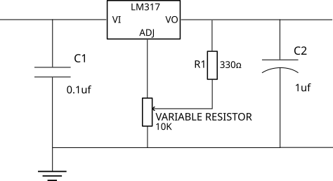
R1 = 240Ω (standard)
R2 = 240Ω × (Vout/1.25V - 1)
Example: For 5V output:
R2 = 240Ω × (5/1.25 - 1) = 1.2kΩ
Input: Vin ≥ Vout + 3V (dropout)
Caps: C_in = 0.1µF, C_out = 1µF, C_adj = 10µF (optional for ripple reduction)
⚡ Zener Diode Regulator
Calculate series resistor for zener voltage regulation
📐 Zener Regulator Formula
Rs = (Vin - Vz) / (Iload + Iz)
PR = (Vin - Vz) × (Iload + Iz)
Pzener = Vz × Iz
Design Tips:
• Iz = 5-10mA for stable regulation
• Add capacitor (100µF) for load transients
• Use next higher standard resistor value
🔄 Buck/Boost Converter Calculator
Design switching regulator inductors and duty cycles
📐 Converter Formulas
D = Vout / Vin
Lmin = (Vin - Vout) × Vout / (ΔI × f × Vin)
Boost Converter:
D = 1 - (Vin / Vout)
Lmin = Vin × D / (ΔI × f)
Buck-Boost:
D = Vout / (Vin + Vout)
ΔI = 20-40% of Iout (ripple current)
🔍 SMD Component Decoder
Decode SMD resistor and capacitor markings
📐 SMD Code Systems
3-digit: XYZ → XY × 10^Z Ω
4-digit: WXYZ → WXY × 10^Z Ω
'R' notation: 4R7 = 4.7Ω, R47 = 0.47Ω
Capacitor Codes:
3-digit: XYZ → XY × 10^Z pF
Letter suffix: pF (A), nF (B), µF (C)
Example: 104 = 100,000pF = 100nF
🎯 E-Series Standard Value Finder
Find nearest standard resistor/capacitor values
📐 E-Series Standards
E12: 12 values/decade (10%, 20%)
E24: 24 values/decade (5%)
E48: 48 values/decade (2%)
E96: 96 values/decade (1%)
Example E12:
10, 12, 15, 18, 22, 27, 33, 39, 47, 56, 68, 82
(multiply by 10^n for other decades)
🔗 Series/Parallel Calculator
Calculate combined resistance and capacitance
📐 Combination Formulas
Series: RT = R1 + R2 + R3 + ...
Parallel: 1/RT = 1/R1 + 1/R2 + 1/R3 + ...
Capacitors (opposite!):
Series: 1/CT = 1/C1 + 1/C2 + 1/C3 + ...
Parallel: CT = C1 + C2 + C3 + ...
🎛️ RL Filter Calculator
Design inductive low-pass and high-pass filters
📐 RL Filter Formulas
fc = R / (2π × L)
L = R / (2π × fc)
Time Constant:
τ = L / R
Impedance:
XL = 2π × f × L (inductive reactance)
📻 RLC Resonant Circuit
Calculate resonance frequency and quality factor
📐 RLC Resonance Formulas
f0 = 1 / (2π × √(L × C))
Quality Factor:
Q = (1/R) × √(L/C) = XL / R
Bandwidth:
BW = f0 / Q
Impedance at Resonance:
Z = R (minimum for series, maximum for parallel)
📡 Wavelength Calculator
Calculate wavelength, frequency, and antenna dimensions
📐 Wavelength Formulas
λ = c / f = (3×10⁸ m/s) / f
λactual = λ × VF (velocity factor)
Antenna Dimensions:
Dipole: λ/2
Quarter-wave: λ/4
Full-wave: λ
Velocity Factors:
Free space: 1.0, Coax (RG-58): 0.66, Wire in air: 0.95
📊 VSWR & Return Loss
Calculate transmission line match quality
📐 VSWR Formulas
VSWR = (1 + |Γ|) / (1 - |Γ|)
Γ = (ZL - Z₀) / (ZL + Z₀) (reflection coefficient)
Return Loss:
RL = -20 × log₁₀(|Γ|) dB
Power Reflected:
Prefl = |Γ|² × 100%
💡 LED Array Calculator
Design series/parallel LED arrays with current limiting
📐 LED Array Design
Nseries = floor(Vsupply / Vf)
Current Limiting Resistor:
R = (Vsupply - N × Vf) / ILED
PR = (Vsupply - N × Vf) × ILED
Parallel Strings:
Nparallel = Total LEDs / Nseries
⏱️ 555 Timer Calculator
Design astable and monostable 555 timer circuits
📐 555 Timer Formulas
f = 1.44 / ((R1 + 2×R2) × C)
Duty Cycle = (R1 + R2) / (R1 + 2×R2) × 100%
Thigh = 0.693 × (R1 + R2) × C
Tlow = 0.693 × R2 × C
Monostable Mode:
Tpulse = 1.1 × R × C
💎 Crystal Oscillator Calculator
Design crystal oscillator load capacitors
📐 Crystal Load Capacitor Formula
CL = (C1 × C2) / (C1 + C2) + Cstray
For equal caps (C1 = C2):
C1 = C2 = 2 × (CL - Cstray)
Typical Values:
CL: 12-22pF (check datasheet)
Cstray: 2-5pF (PCB + pin capacitance)
🔺 BJT Bias Calculator
Design voltage divider bias for BJT amplifiers
📐 BJT Biasing Formulas
VE = 0.1 × VCC (rule of thumb)
VB = VE + 0.7V (silicon BJT)
RE = VE / IE ≈ VE / IC
RC = (VCC - VCE - VE) / IC
Base Resistors:
Idivider = 10 × IB = 10 × IC / β
R2 = VB / Idivider
R1 = (VCC - VB) / Idivider
🎛️ MOSFET Gate Drive Calculator
Calculate gate resistor and switching times
📐 MOSFET Gate Drive Formulas
Rgate = tswitch / (2.2 × Ciss)
Switching Time:
trise/fall ≈ 2.2 × Rgate × Ciss
Peak Gate Current:
Igate(peak) = Vdrive / Rgate
Power Dissipation:
Psw = Ciss × Vdrive² × fsw
📈 Op-Amp Gain Calculator
Design inverting and non-inverting amplifier circuits
📐 Op-Amp Gain Formulas
Av = 1 + (R2 / R1)
Vout = Vin × Av
Inverting:
Av = -(R2 / R1)
Vout = -Vin × (R2 / R1)
Zin = R1
Differential:
Vout = (R2/R1) × (V2 - V1)
Inverting Amplifier — Example
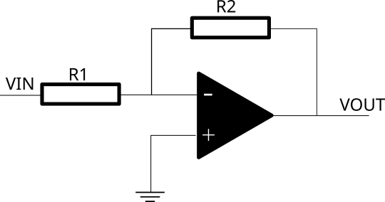
Example: R1 = 10 kΩ, R2 = 100 kΩ → Av = -10
Non-Inverting Amplifier — Example
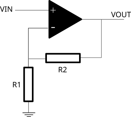
Example: R1 = 10 kΩ, R2 = 90 kΩ → Av = 10
Differential Amplifier — Example
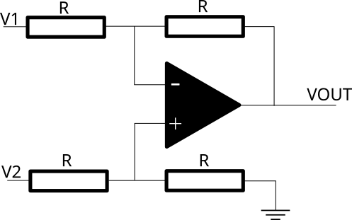
Example: R1 = 10 kΩ, R2 = 10 kΩ → unity differential gain
🔌 RS-485 Termination Calculator
Calculate termination resistors for RS-485 networks
📐 RS-485 Design Rules
Rterm = Z₀ (cable impedance, typically 120Ω)
Place at both ends of the bus
Bias Resistors (optional):
Rpullup = Rpulldown ≈ 560Ω
Ensures defined idle state
Cable Length Limits:
115200 baud: ~1200m
1 Mbaud: ~100m
10 Mbaud: ~12m
⚡ KVL/KCL Circuit Solver
Solve simple series and parallel circuits using Kirchhoff's Laws
📐 Kirchhoff's Laws
ΣV = 0 (sum of voltages in closed loop = 0)
Vsource = VR1 + VR2 + VR3 + ...
Kirchhoff's Current Law (KCL):
ΣI = 0 (sum of currents at node = 0)
Iin = Iout1 + Iout2 + Iout3 + ...
Series: Same current, voltages add
Parallel: Same voltage, currents add
⚖️ Wheatstone Bridge
Find an unknown resistance using a balanced bridge circuit. When balanced: R1/R2 = R3/R4
📐 Wheatstone Bridge Theory
R1/R2 = R3/R4 → Vout = 0V
Find Unknown R:
R4 = R2 × R3 / R1
Output Voltage (unbalanced):
Vout = Vs × (R4/(R3+R4) − R2/(R1+R2))
Common Uses:
• Strain gauges & load cells
• Temperature sensors (thermistors)
• Pressure sensors
• Precise resistance measurement
🌡️ Heatsink & Thermal Calculator
Calculate junction temperature and required heatsink thermal resistance
📐 Thermal Resistance Chain
Tj = Ta + P × (θjc + θcs + θsa)
Required Heatsink θsa:
θsa = (Tj_max − Ta) / P − θjc − θcs
Typical Values:
θcs with thermal paste: 0.1–0.5 °C/W
θcs dry / mica pad: 0.5–1.5 °C/W
Free-air heatsink: 5–30 °C/W
Forced-air heatsink: 1–10 °C/W
🔥 Fuse Sizing Calculator
Select the correct fuse rating for a circuit
📐 Standard Fuse Ratings
0.1, 0.16, 0.2, 0.25, 0.315, 0.4, 0.5, 0.63,
0.8, 1, 1.25, 1.6, 2, 2.5, 3.15, 4, 5, 6.3,
8, 10, 12.5, 16, 20, 25, 32, 40, 50, 63A
Rule of thumb:
Fuse rating = Load current × safety margin
Round UP to next standard value
Fast-blow: Signal/semiconductor protection
Slow-blow: Motors, transformers, PSUs
Anti-surge: General electronics
🔄 Transformer Calculator
Turns ratio, secondary voltage/current, and efficiency
📐 Transformer Formulas
Secondary Voltage: Vs = Vp × Ns/Np
Secondary Current: Is = Ip × Np/Ns × η
Output Power: Pout = Vs × Is
Efficiency: η = Pout / Pin × 100%
Note: After rectification, DC voltage
≈ Vs(rms) × 1.414 − 1.4V (bridge losses)
⚡ Capacitor Energy & Charge
Energy stored, charge time, and discharge calculations
📐 Capacitor Formulas
Charge Stored: Q = C × V (Coulombs)
RC Time Constant: τ = R × C
63.2% charged at 1τ, 99.3% at 5τ
Charge Time (to % of V):
t = −τ × ln(1 − V_target/V_supply)
Capacitive Reactance:
Xc = 1 / (2π × f × C)
⚡ Inrush Current & NTC Sizing
Calculate inrush current and select NTC thermistor limiter
📐 Inrush Theory
V_peak = V_rms × √2 ≈ V_rms × 1.414
NTC Thermistor Sizing:
R_ntc_cold = V_peak / I_max_allowed
Choose NTC with R25 ≥ this value
Steady-state loss = I²ss × R_ntc_hot
Rule of thumb:
Inrush can be 20–100× steady-state current
NTC reduces this to 3–10× safely
Alternatives: Series resistor + relay bypass,
active inrush controller ICs (e.g. TPS2490)
📉 Component Derating Calculator
Calculate safe operating limits with temperature derating
📐 Derating Guidelines
Full power to 70°C, derate to 0W at 155°C
P_safe = P_rated × (155 − T_op) / (155 − 70)
Capacitors:
Voltage derate 50–80% of rated voltage
Electrolytic: never exceed 80% V_rated
Ceramic: 50% for long-term reliability
Semiconductors:
Current derate linearly above 25°C
I_safe = I_rated × (Tj_max − T_op) / (Tj_max − 25)
🔌 Wire Gauge Calculator (AWG ↔ mm²)
Convert between AWG and metric, find current capacity and resistance
📐 Quick AWG Reference
Area (mm²): A = π/4 × d²
Resistance (Ω/km, copper):
R = ρ / A = 0.01724 / A(mm²) × 1000
Common cable sizes (IEC):
0.5 mm² — signalling, 3A
1.0 mm² — lighting, 10A
1.5 mm² — ring mains, 16A
2.5 mm² — sockets, 20A
4.0 mm² — cooker/shower, 25A
6.0 mm² — sub-mains, 32A
10 mm² — supply tails, 43A
📉 Cable Voltage Drop Calculator
Calculate voltage drop over a cable run
📐 Voltage Drop Limits
R_cable = ρ × (2L) / A
V_drop = I × R_cable
Acceptable Limits:
Mains wiring (IEC 60364): ≤ 3% (lighting), ≤ 5% (power)
12V automotive: ≤ 3% (≤ 0.36V)
24V systems: ≤ 3% (≤ 0.72V)
Low-voltage signal: ≤ 1%
Rule of thumb:
Double cable length = double voltage drop
Double cable area = half voltage drop
📊 dB Converter
Convert between dB, voltage ratio, and power ratio
📐 Common dB Values
Power: dB = 10 × log₁₀(Pout/Pin)
Key values to memorise:
+3 dB = ×2 power, ×1.414 voltage
+6 dB = ×4 power, ×2 voltage
+10 dB = ×10 power, ×3.16 voltage
+20 dB = ×100 power, ×10 voltage
−3 dB = ½ power (−3dB point = cutoff freq)
−6 dB = ¼ power, ½ voltage
−20 dB = 1/100 power, 1/10 voltage
dBm: power relative to 1mW
0 dBm = 1mW, +30 dBm = 1W
🔢 ADC / DAC Resolution Calculator
LSB voltage, full-scale range, quantisation noise, and SNR
📐 ADC / DAC Formulas
LSB = Vref / 2^N
Theoretical SNR:
SNR = 6.02 × N + 1.76 dB
Digital code to voltage:
V = code × Vref / (2^N − 1)
Effective Number of Bits (ENOB):
ENOB = (SINAD − 1.76) / 6.02
Common Vref sources:
3.3V MCU supply, 5V supply,
2.048V / 2.5V / 4.096V precision ref ICs
🌊 PWM → Average Voltage Calculator
Calculate average voltage, RC filter values, and ripple
📐 PWM Filter Design
Vavg = Vsupply × (duty / 100)
RC Low-Pass Filter:
fc = 1 / (2π × R × C)
For good filtering: fc < PWM freq / 10
Ripple Voltage (approx):
Vripple ≈ Vavg / (f × R × C)
Use case examples:
LED dimming, motor speed control,
DAC replacement (with RC filter),
servo control (50Hz, 1–2ms pulse)
〰️ Schmitt Trigger / Comparator Hysteresis
Design hysteresis window for noise-immune threshold detection
📐 Schmitt Trigger Formulas
V_upper = Vcc × R1 / (R1 + R2)
V_lower = 0 × R1 / (R1 + R2) = 0 (rail-to-rail)
Hysteresis:
Vhyst = V_upper − V_lower
R2 = R1 × (Vcc − Vhyst) / Vhyst
Use when:
• Noisy signal crosses threshold
• Slow-moving signals (thermistors, LDRs)
• Converting sine waves to square waves
• Debouncing mechanical switches
🔐 CRC Calculator
Calculate CRC checksums for data verification
📐 CRC Reference
CRC-8/MAXIM: Dallas 1-Wire, DS18B20
CRC-16: USB, Bluetooth
CRC-16/CCITT: SD cards, Xmodem
CRC-16/MODBUS: RS-485 Modbus RTU
CRC-32: Ethernet, ZIP, PNG files
Input format:
Hex pairs separated by spaces:
01 A2 FF 3C → 4 bytes
Use case:
Verify your microcontroller CRC matches
protocol spec before deploying to production